Building Blocks - Applications
Here are some examples that use the basic PRU building blocks.
The following are resources used in this chapter.
Note
Resources
Memory Allocation
Problem
I want to control where my variables are stored in memory.
Solution
Each PRU has is own 8KB of data memory (Data Mem0 and Mem1) and 12KB of shared memory (Shared RAM) as shown in PRU Block Diagram.
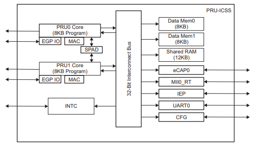
Fig. 359 PRU Block Diagram
Each PRU accesses its own DRAM starting at location 0x0000_0000. Each PRU can also access the other PRU’s DRAM starting at 0x0000_2000. Both PRUs access the shared RAM at 0x0001_0000. The compiler can control where each of these memories variables are stored.
blocks_shared shows how to allocate seven variable in six different locations.
Discussion
Here’s the line-by-line
Line |
Explanation |
|---|---|
7 |
PRU_SRAM is defined here. It will be used later to declare variables in the Shared RAM location of memory. Section 5.5.2 on page 75 of the PRU Optimizing C/C++ Compiler, v2.2, User’s Guide gives details of the command. The PRU_SHAREDMEM refers to the memory section defined in am335x_pru.cmd on line 26. |
8, 9 |
These are like the previous line except for the DMEM sections. |
16 |
Variables declared outside of main() are put on the heap. |
17 |
Adding PRU_SRAM has the variable stored in the shared memory. |
18, 19 |
These are stored in the PRU’s local RAM. |
20, 21 |
These lines are for storing in the .bss section as declared on line 74 of am335x_pru.cmd. |
28-31 |
All the previous examples direct the compiler to an area in memory and the compilers figures out what to put where. With these lines we specify the exact location. Here are start with the PRU_DRAM starting address and add 0x200 to it to avoid the stack and the heap. The advantage of this technique is you can easily share these variables between the ARM and the two PRUs. |
36, 37 |
Variable declared inside main() go on the stack. |
Caution
Using the technique of line 28-31 you can put variables anywhere, even where the compiler has put them. Be careful, it’s easy to overwrite what the compiler has done
Compile and run the program.
bone$ *source shared_setup.sh*
TARGET=shared.pru0
Black Found
P9_31
Current mode for P9_31 is:     pruout
Current mode for P9_31 is:     pruout
P9_29
Current mode for P9_29 is:     pruout
Current mode for P9_29 is:     pruout
P9_30
Current mode for P9_30 is:     pruout
Current mode for P9_30 is:     pruout
P9_28
Current mode for P9_28 is:     pruout
Current mode for P9_28 is:     pruout
bone$ *make*
/var/lib/cloud9/common/Makefile:29: MODEL=TI_AM335x_BeagleBone_Black,TARGET=shared.pru0
-    Stopping PRU 0
-     copying firmware file /tmp/cloud9-examples/shared.pru0.out to /lib/firmware/am335x-pru0-fw
write_init_pins.sh
-    Starting PRU 0
MODEL   = TI_AM335x_BeagleBone_Black
PROC    = pru
PRUN    = 0
PRU_DIR = /sys/class/remoteproc/remoteproc1
Now check the symbol table to see where things are allocated.
bone $ *grep shared /tmp/cloud9-examples/shared.pru0.map*
....
1     0000011c  shared_0
2     00010000  shared_1
1     00000000  shared_2
1     00002000  shared_3
1     00000118  shared_4
1     00000120  shared_5
We see, shared_0 had no directives and was places in the heap that is 0x100
to 0x1ff. shared_1 was directed to go to the SHAREDMEM, shared_2 to
the start of the local DRAM (which is also the top of the stack). shared_3
was placed in the DRAM of PRU 1, shared_4 was placed in the .bss section,
which is in the heap. Finally shared_5 is a pointer to where the value
is stored.
Where are shared_6 and shared_7? They are declared inside main() and are
therefore placed on the stack at run time. The shared.map file shows the
compile time allocations. We have to look in the memory itself to see what
happen at run time.
Let’s fire up prudebug (prudebug - A Simple Debugger for the PRU) to see where things are.
bone$ *sudo ./prudebug*
PRU Debugger v0.25
(C) Copyright 2011, 2013 by Arctica Technologies.  All rights reserved.
Written by Steven Anderson

Using /dev/mem device.
Processor type                AM335x
PRUSS memory address  0x4a300000
PRUSS memory length   0x00080000

        offsets below are in 32-bit byte addresses (not ARM byte addresses)
        PRU            Instruction    Data         Ctrl
        0              0x00034000     0x00000000   0x00022000
        1              0x00038000     0x00002000   0x00024000

PRU0> *d 0*
Absolute addr = 0x0000, offset = 0x0000, Len = 16
[0x0000] 0x0000feed 0x00000000 0x00000000 0x00000000
[0x0010] 0x00000000 0x00000000 0x00000000 0x00000000
[0x0020] 0x00000000 0x00000000 0x00000000 0x00000000
[0x0030] 0x00000000 0x00000000 0x00000000 0x00000000
The value of shared_2 is in memory location 0.
PRU0> *dd 0x100*
Absolute addr = 0x0100, offset = 0x0000, Len = 16
[0x0100] 0x00000000 0x00000001 0x00000000 0x00000000
[0x0110] 0x00000000 0x00000000 0x0000beed 0x0000feef
[0x0120] 0x00000200 0x3ec71de3 0x1a013e1a 0xbf2a01a0
[0x0130] 0x111110b0 0x3f811111 0x55555555 0xbfc55555
There are shared_0 and shared_4 in the heap, but where is shared_6 and
shared_7? They are supposed to be on the stack that starts at 0.
PRU0> dd *0xc0*
Absolute addr = 0x00c0, offset = 0x0000, Len = 16
[0x00c0] 0x00000000 0x00000000 0x00000000 0x00000000
[0x00d0] 0x00000000 0x00000000 0x00000000 0x00000000
[0x00e0] 0x00000000 0x00000000 0x00000000 0x00000000
[0x00f0] 0x00000000 0x00000000 0x00004321 0x00009876
There they are; the stack grows from the top. (The heap grows from the bottom.)
PRU0> dd *0x2000*
Absolute addr = 0x2000, offset = 0x0000, Len = 16
[0x2000] 0x0000deed 0x00000001 0x00000000 0x557fcfb5
[0x2010] 0xce97bd0f 0x6afb2c8f 0xc7f35df4 0x5afb6dcb
[0x2020] 0x8dec3da3 0xe39a6756 0x642cb8b8 0xcb6952c0
[0x2030] 0x2f22ebda 0x548d97c5 0x9241786f 0x72dfeb86
And there is PRU 1’s memory with shared_3. And finally the shared memory.
PRU0> *dd 0x10000*
Absolute addr = 0x10000, offset = 0x0000, Len = 16
[0x10000] 0xdeadbeef 0x0000feed 0x00000000 0x68c44f8b
[0x10010] 0xc372ba7e 0x2ffa993b 0x11c66da5 0xfbf6c5d7
[0x10020] 0x5ada3fcf 0x4a5d0712 0x48576fb7 0x1004796b
[0x10030] 0x2267ebc6 0xa2793aa1 0x100d34dc 0x9ca06d4a
The compiler offers great control over where variables are stored. Just be sure if you are hand picking where things are put, not to put them in places used by the compiler.
Auto Initialization of built-in LED Triggers
Problem
I see the built-in LEDs blink to their own patterns. How do I turn this off? Can this be automated?
Solution
Each built-in LED has a default action (trigger) when the Bone boots up.
This is controlled by /sys/class/leds.
bone$ *cd /sys/class/leds*
bone$ *ls*
beaglebone:green:usr0  beaglebone:green:usr2
beaglebone:green:usr1  beaglebone:green:usr3
Here you see a directory for each of the LEDs. Let’s pick USR1.
bone$ *cd beaglebone\:green\:usr1*
bone$ *ls*
brightness  device  max_brightness  power  subsystem  trigger  uevent
bone$ *cat trigger*
none usb-gadget usb-host rfkill-any rfkill-none kbd-scrolllock kbd-numlock
kbd-capslock kbd-kanalock kbd-shiftlock kbd-altgrlock kbd-ctrllock kbd-altlock
kbd-shiftllock kbd-shiftrlock kbd-ctrlllock kbd-ctrlrlock *[mmc0]* timer
oneshot disk-activity disk-read disk-write ide-disk mtd nand-disk heartbeat
backlight gpio cpu cpu0 activity default-on panic netdev phy0rx phy0tx
phy0assoc phy0radio rfkill0
Notice [mmc0] is in brackets. This means it’s the current trigger; it flashes
when the built-in flash memory is in use. You can turn this off using:
bone$ *echo none > trigger*
bone$ *cat trigger*
*[none]* usb-gadget usb-host rfkill-any rfkill-none kbd-scrolllock kbd-numlock
kbd-capslock kbd-kanalock kbd-shiftlock kbd-altgrlock kbd-ctrllock kbd-altlock
kbd-shiftllock kbd-shiftrlock kbd-ctrlllock kbd-ctrlrlock mmc0 timer
oneshot disk-activity disk-read disk-write ide-disk mtd nand-disk heartbeat
backlight gpio cpu cpu0 activity default-on panic netdev phy0rx phy0tx
phy0assoc phy0radio rfkill0
Now it is no longer flashing.
How can this be automated so when code is run that needs the trigger off, it’s turned off automatically? Here’s a trick. Include the following in your code.
1#pragma DATA_SECTION(init_pins, ".init_pins")
2#pragma RETAIN(init_pins)
3const char init_pins[] =
4        "/sys/class/leds/beaglebone:green:usr3/trigger\0none\0" \
5        "\0\0";
Lines 3 and 4 declare the array init_pins to have an entry which is the path
to trigger and the value that should be ‘echoed’ into it. Both are NULL
terminated. Line 1 says to put this in a section called .init_pins and
line 2 says to RETAIN it. That is don’t throw it away if it appears to be
unused.
Discussion
The above code stores this array in the .out file thats created, but that’s not
enough. You need to run blocks_write_init_pins on the .out file to make
the code work. Fortunately the Makefile always runs it.
write_init_pins.sh
The readelf command extracts the path and value from the .out file.
bone$ *readelf -x .init_pins /tmp/pru0-gen/shared.out*

Hex dump of section '.init_pins':
  0x000000c0 2f737973 2f636c61 73732f6c 6564732f /sys/class/leds/
  0x000000d0 62656167 6c65626f 6e653a67 7265656e beaglebone:green
  0x000000e0 3a757372 332f7472 69676765 72006e6f :usr3/trigger.no
  0x000000f0 6e650000 0000                       ne....
The rest of the command formats it. Finally line 6 echos the none into the path.
This can be generalized to initialize other things. The point is, the .out
file contains everything needed to run the executable.
PWM Generator
One of the simplest things a PRU can to is generate a simple signal starting with a single channel PWM that has a fixed frequency and duty cycle and ending with a multi channel PWM that the ARM can change the frequency and duty cycle on the fly.
Problem
I want to generate a PWM signal that has a fixed frequency and duty cycle.
Solution
The solution is fairly easy, but be sure to check the Discussion section for details on making it work.
blocks_pwm1 shows the code.
Warning
This code is for the BeagleBone Black.
See pwm1.pru1_1.c for an example
that works on the AI.
pwm1.pru0.c
To run this code you need to configure the pin muxes to output the PRU. If you are on the Black run
bone$ config-pin P9_31 pruout
On the Pocket run
bone$ config-pin P1_36 pruout
Note
See Configuring pins on the AI via device trees for configuring pins on the AI.
Then, tell Makefile which PRU you are compiling for and what your target file is
bone$ export TARGET=pwm1.pru0
Now you are ready to compile
bone$ make
/var/lib/cloud9/common/Makefile:29: MODEL=TI_AM335x_BeagleBone_Black,TARGET=pwm1.pru0
-    Stopping PRU 0
-     copying firmware file /tmp/cloud9-examples/pwm1.pru0.out to /lib/firmware/am335x-pru0-fw
write_init_pins.sh
-    Starting PRU 0
MODEL   = TI_AM335x_BeagleBone_Black
PROC    = pru
PRUN    = 0
PRU_DIR = /sys/class/remoteproc/remoteproc1
Now attach an LED (or oscilloscope) to P9_31 on the Black
or P1.36 on the Pocket. You should see a squarewave.
Discussion
Since this is our first example we’ll discuss the many parts in detail.
pwm1.pru0.c
Line-by-line of pwm1.pru0.c is a line-by-line expanation of the c code.
Line |
Explanation |
|---|---|
1 |
Standard c-header include |
2 |
Include for the PRU. The compiler knows where to find this since the Makefile says to look for includes in /usr/lib/ti/pru-software-support-package |
3 |
The file resource_table_empty.h is used by the PRU loader. Generally we’ll use the same file, and don’t need to modify it. |
4 |
This include has addresses for the GPIO ports and some bit positions for some of the headers. |
Here’s what’s in resource_table_empty.h
resource_table_empty.c
Line |
Explanation |
|---|---|
6-7 |
|
11 |
This line selects which GPIO pin to toggle. The table below shows which bits in |
14 |
CT_CFG.SYSCFG_bit.STANDBY_INIT is set to 0 to enable the OCP master port. More details on this and thousands of other regesters see the TI AM335x TRM. Section 4 is on the PRU and section 4.5 gives details for all the registers. |
Bit 0 is the LSB.
PRU |
Bit |
Black pin |
Pocket pin |
|---|---|---|---|
0 |
0 |
P9_31 |
P1.36 |
0 |
1 |
P9_29 |
P1.33 |
0 |
2 |
P9_30 |
P2.32 |
0 |
3 |
P9_28 |
P2.30 |
0 |
4 |
P9_42b |
P1.31 |
0 |
5 |
P9_27 |
P2.34 |
0 |
6 |
P9_41b |
P2.28 |
0 |
7 |
P9_25 |
P1.29 |
0 |
14 |
P8_12(out) P8_16(in) |
P2.24 |
0 |
15 |
P8_11(out) P8_15(in) |
P2.33 |
1 |
0 |
P8_45 |
|
1 |
1 |
P8_46 |
|
1 |
2 |
P8_43 |
|
1 |
3 |
P8_44 |
|
1 |
4 |
P8_41 |
|
1 |
5 |
P8_42 |
|
1 |
6 |
P8_39 |
|
1 |
7 |
P8_40 |
|
1 |
8 |
P8_27 |
P2.35 |
1 |
9 |
P8_29 |
P2.01 |
1 |
10 |
P8_28 |
P1.35 |
1 |
11 |
P8_30 |
P1.04 |
1 |
12 |
P8_21 |
|
1 |
13 |
P8_20 |
|
1 |
14 |
P1.32 |
|
1 |
15 |
P1.30 |
|
1 |
16 |
P9_26(in)| |
Note
See Configuring pins on the AI via device trees for all the PRU pins on the AI.
Since we are running on PRU 0, and we’re using 0x0001,
that is bit 0, we’ll be toggling P9_31.
Line |
Explanation |
|---|---|
17 |
Here is where the action is. This line reads |
18 |
|
19 |
This is like line 17, but |
Tip
You can read more about intrinsics in section 5.11 of the (PRU Optimizing C/C++ Compiler, v2.2, User’s Guide.)
When you run this code and look at the output you will see something like the following figure.
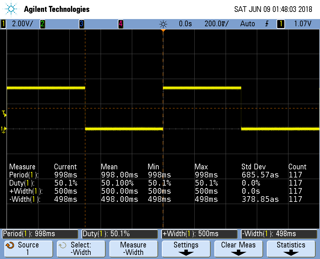
Fig. 360 Output of pwm1.pru0.c with 100,000,000 delays cycles giving a 1s period
Notice the on time (+Width(1)) is 500ms, just as we predicted.
The off time is 498ms, which is only 2ms off from our prediction.
The standard deviation is 0, or only 380as, which is 380 * 10^-18^!.
You can see how fast the PRU can run by setting both of the
__delay_cycles to 0. This results in the next figure.

Fig. 361 Output of pwm1.pru0c with 0 delay cycles
Notice the period is 15ns which gives us a frequency of about 67MHz. At this high
frequency the breadboard that I’m using distorts the waveform so it’s no longer a squarewave.
The on time is 5.3ns and the off time is 9.8ns. That means __R30 |= gpio
took only one 5ns cycle and __R30 &= ~gpio also only took one cycle, but there
is also an extra cycle needed for the loop. This means the compiler was able to implement
the while loop in just three 5ns instructions! Not bad.
We want a square wave, so we need to add a delay to correct for the delay of looping back.
Here’s the code that does just that.
pwm2.pru0.c
The output now looks like:
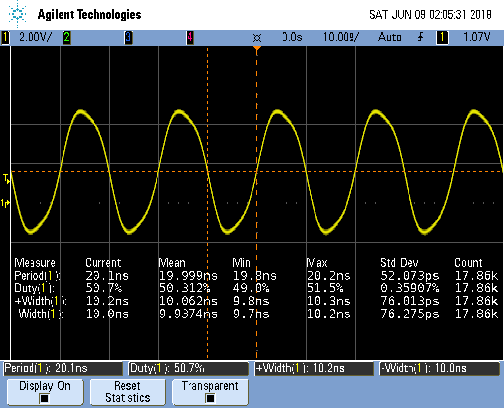
Fig. 362 Output of pwm2.pru0.c corrected delay
It’s not hard to adjust the two __delay_cycles
to get the desired frequency and duty cycle.
Controlling the PWM Frequency
Problem
You would like to control the frequency and duty cycle of the PWM without recompiling.
Solution
Have the PRU read the on and off times from a shared memory location. Each PRU has is own 8KB of data memory (DRAM) and 12KB of shared memory (SHAREDMEM) that the ARM processor can also access. See PRU Block Diagram.
The DRAM 0 address is 0x0000 for PRU 0. The same DRAM appears at address 0x4A300000 as seen from the ARM processor.
Tip
See page 184 of the AM335x TRM (184).
We take the previous PRU code and add the lines
#define PRU0_DRAM             0x00000                 // Offset to DRAM
volatile unsigned int *pru0_dram = PRU0_DRAM;
to define a pointer to the DRAM.
Note
The volatile keyword is used here to tell the compiler the value this points to may change, so don’t make any assumptions while optimizing.
Later in the code we use
pru0_dram[ch] = on[ch];             // Copy to DRAM0 so the ARM can change it
pru0_dram[ch+MAXCH] = off[ch];  // Copy after the on array
to write the on and off times to the DRAM. Then inside the while loop we use
onCount[ch] = pru0_dram[2*ch];          // Read from DRAM0
offCount[ch]= pru0_dram[2*ch+1];
to read from the DRAM when resetting the counters. Now, while the PRU is running, the ARM can write values into the DRAM and change the PWM on and off times. blocks_pwm4 is the whole code.
pwm4.pru0.c
Here is code that runs on the ARM side to set the on and off time values.
pwm-test.c
A quick check on the ‘scope shows Four Channel PWM with ARM control.
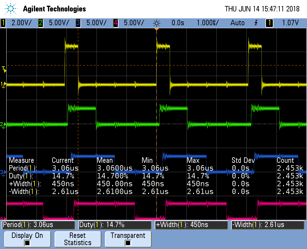
Fig. 363 Four Channel PWM with ARM control
From the ‘scope you see a 1 cycle on time results in a 450ns wide pulse and a 3.06us period is 326KHz, much slower than the 10ns pulse we saw before. But it may be more than fast enough for many applications. For example, most servos run at 50Hz.
But we can do better.
Loop Unrolling for Better Performance
Problem
The ARM controlled PRU code runs too slowly.
Solution
Simple loop unrolling can greatly improve the speed. pwm5.pru0.c is our unrolled version.
pwm5.pru0.c
The output of pwm5.pru0.c is in the figure below.
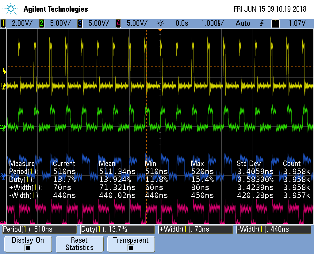
Fig. 364 pwm5.pru0.c Unrolled version of pwm4.pru0.c
It’s running about 6 times faster than pwm4.pru0.c.
Measure |
pwm4.pru0.c time |
pwm5.pru0.c time |
Speedup |
pwm5.pru0.c w/o UNROLL |
Speedup |
Period |
3.06μs |
510ns |
6x |
1.81μs |
~1.7x |
Width+ |
450ns |
70ns |
~6x |
1.56μs |
~.3x |
Not a bad speed up for just a couple of simple changes.
Discussion
Here’s how it works.
First look at line 39. You see #pragma UNROLL(MAXCH) which is a pragma
that tells the compiler to unroll the loop that follows. We are unrolling it
MAXCH times (four times in this example). Just removing the pragma causes
the speedup compared to the pwm4.pru0.c case to drop from 6x to only 1.7x.
We also have our for loop inside the while loop that can be unrolled.
Unfortunately UNROLL() doesn’t work on it, therefore we have to do it by
hand. We could take the loop and just copy it three times, but that would
make it harder to maintain the code. Instead I converted the loop into a
#define (lines 14-24) and invoked update() as needed (lines 48-51).
This is not a function call. Whenever the preprocessor sees the update()
it copies the code an then it’s compiled.
This unrolling gets us an impressive 6x speedup.
Making All the Pulses Start at the Same Time
Problem
I have a mutlichannel PWM working, but the pulses aren’t synchronized, that is they don’t all start at the same time.
Solution
pwm5.pru0 Zoomed In is a zoomed in version of the previous figure. Notice the pulse in each channel starts about 15ns later than the channel above it.
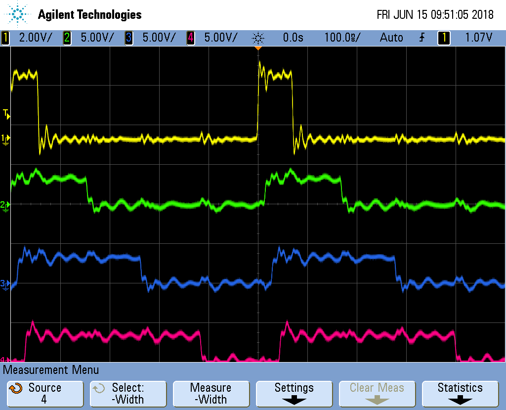
Fig. 365 pwm5.pru0 Zoomed In
The solution is to declare Rtmp (line 35) which holds the value for __R30.
pwm6.pru0.c Sync'ed Version of pwm5.pru0.c
Each channel writes it’s value to Rtmp (lines 17 and 20) and then after
each channel has updated, Rtmp is copied to __R30 (line 54).
Discussion
The following figure shows the channel are sync’ed. Though the period is slightly longer than before.
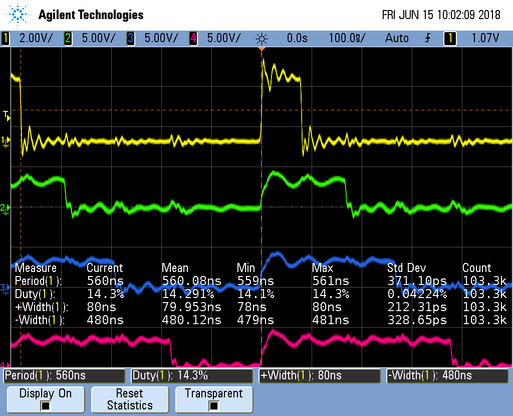
Fig. 366 pwm6.pru0 Synchronized Channels
Adding More Channels via PRU 1
Problem
You need more output channels, or you need to shorten the period.
Solution
PRU 0 can output up to eight output pins (see Mapping bit positions to pin names). The code presented so far can be easily extended to use the eight output pins.
But what if you need more channels? You can always use PRU1, it has 14 output pins.
Or, what if four channels is enough, but you need a shorter period. Everytime you add a channel, the overall period gets longer. Twice as many channels means twice as long a period. If you move half the channels to PRU 1, you will make the period half as long.
Here’s the code (pwm7.pru0.c)
pwm7.pru0.c Using Both PRUs
Be sure to run pwm7_setup.sh to get the correct pins configured.
pw7_setup.sh
This makes sure the PRU 1 pins are properly configured.
Here we have a second pwm7 file. pwm7.pru1.c is identical to pwm7.pru0.c
except PRUNUM is set to 1, instead of 0.
Compile and run the two files with:
bone$ *make TARGET=pwm7.pru0; make TARGET=pwm7.pru1*
/var/lib/cloud9/common/Makefile:29: MODEL=TI_AM335x_BeagleBone_Black,TARGET=pwm7.pru0
-    Stopping PRU 0
-     copying firmware file /tmp/cloud9-examples/pwm7.pru0.out to /lib/firmware/am335x-pru0-fw
write_init_pins.sh
-    Starting PRU 0
MODEL   = TI_AM335x_BeagleBone_Black
PROC    = pru
PRUN    = 0
PRU_DIR = /sys/class/remoteproc/remoteproc1
/var/lib/cloud9/common/Makefile:29: MODEL=TI_AM335x_BeagleBone_Black,TARGET=pwm7.pru1
-    Stopping PRU 1
-     copying firmware file /tmp/cloud9-examples/pwm7.pru1.out to /lib/firmware/am335x-pru1-fw
write_init_pins.sh
-    Starting PRU 1
MODEL   = TI_AM335x_BeagleBone_Black
PROC    = pru
PRUN    = 1
PRU_DIR = /sys/class/remoteproc/remoteproc2
This will first stop, compile and start PRU 0, then do the same for PRU 1.
Moving half of the channels to PRU1 dropped the period from 510ns to 370ns, so we gained a bit.
Discussion
There weren’t many changes to be made. Line 15 we set MAXCH to 2. Lines 44-48 is where the big change is.
pru0_dram[2*ch  ] = on [ch+PRUNUN*MAXCH];       // Copy to DRAM0 so the ARM can change it
pru0_dram[2*ch+1] = off[ch+PRUNUN*MAXCH];       // Interleave the on and off values
onCount[ch] = on [ch+PRUNUN*MAXCH];
offCount[ch]= off[ch+PRUNUN*MAXCH];
If we are compiling for PRU 0, on[ch+PRUNUN*MAXCH] becomes on[ch+0*2] which is
on[ch] which is what we had before. But now if we are on PRU 1 it becomes
on[ch+1*2] which is on[ch+2]. That means we are picking up the second
half of the on and off arrays. The first half goes to PRU 0, the second to
PRU 1. So the same code can be used for both PRUs, but we get slightly different
behavior.
Running the code you will see the next figure.
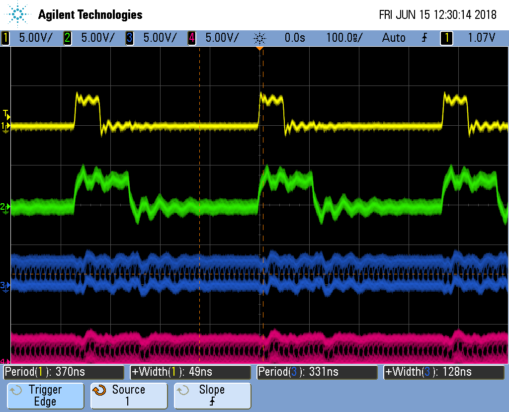
Fig. 367 pwm7.pru0 Two PRUs running
What’s going on there, the first channels look fine, but the PRU 1 channels are blurred. To see what’s happening, let’s stop the oscilloscope.
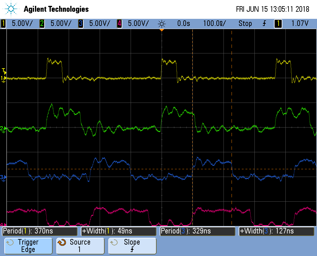
Fig. 368 pwm7.pru0 Two PRUs stopped
The stopped display shows that the four channels are doing what we wanted, except The PRU 0 channels have a period of 370ns while the PRU 1 channels at 330ns. It appears the compiler has optimied the two PRUs slightly differently.
Synchronizing Two PRUs
Problem
I need to synchronize the two PRUs so they run together.
Solution
Use the Interrupt Controller (INTC). It allows one PRU to signal the other.
Page 225 of the AM335x TRM 225
has details of how it works. Here’s the code for PRU 0, which at the end of the
while loop signals PRU 1 to start(pwm8.pru0.c).
pwm8.pru0.c PRU 0 using INTC to send a signal to PRU 1
PRU 2’s code waits for PRU 0 before going.
pwm8.pru1.c PRU 1 waiting for INTC from PRU 0
In pwm8.pru0.c PRU 1 waits for a signal from PRU 0, so be sure to start PRU 1 first.
bone$ *make TARGET=pwm8.pru0; make TARGET=pwm8.pru1*
Discussion
The figure below shows the two PRUs are synchronized, though there is some extra overhead in the process so the period is longer.
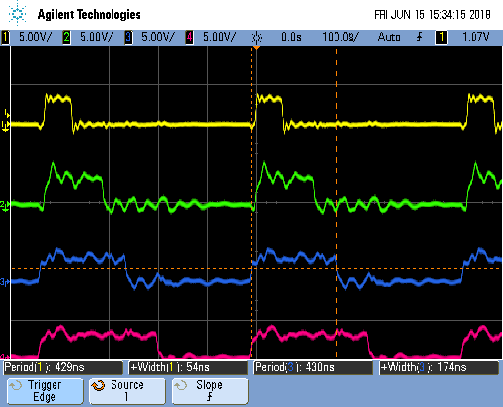
Fig. 369 pwm8.pru0 PRUs synced
This isn’t much different from the previous examples.
PRU |
Line |
Change |
|---|---|---|
0 |
37-45 |
For PRU 0 these define |
0 |
55-56 |
Set a configuration register and call configInitc. |
1 |
59-61 |
PRU 1 then waits for PRU 0 to signal it. Bit 31 of |
0 |
74-75 |
On PRU 0 this generates the interrupt to send to PRU 1. I found PRU 1 was slow to respond to the interrupt, so I put this code at the end of the loop to give time for the signal to get to PRU 1. |
This ends the multipart pwm example.
Reading an Input at Regular Intervals
Problem
You have an input pin that needs to be read at regular intervals.
Solution
You can use the __R31 register to read an input pin. Let’s use the following pins.
Direction |
Bit number |
Black |
AI (ICSS2) |
|
|---|---|---|---|---|
out |
0 |
P9_31 |
P8_44 |
P1.36 |
in |
7 |
P9_25 |
P8_36 |
P1.29 |
These values came from Mapping bit positions to pin names.
Configure the pins with input_setup.sh.
input_setup.sh
The following code reads the input pin and writes its value to the output pin.
input.pru0.c
Discussion
Just remember that __R30 is for outputs and __R31 is for inputs.
Analog Wave Generator
Problem
I want to generate an analog output, but only have GPIO pins.
Solution
The Beagle doesn’t have a built-in analog to digital converter. You could get a USB Audio Dongle which are under $10. But here we’ll take another approach.
Earlier we generated a PWM signal. Here we’ll generate a PWM whose duty cycle changes with time. A small duty cycle for when the output signal is small and a large duty cycle for when it is large.
This example was inspired by A PRU Sin Wave Generator in chapter 13 of Exploring BeagleBone by Derek Molloy.
Here’s the code.
sine.pru0.c
Set the #define at line 7 to the number of samples in one cycle of the waveform
and set the #define at line 8 to which waveform and then run make.
Discussion
The code has two parts. The first part (lines 21 to 39) generate the waveform
to be output. The #define``s let you select which waveform you want to
generate. Since the output is a percent duty cycle, the values in ``waveform[]
must be between 0 and 100 inclusive. The waveform is only generated once, so
this part of the code isn’t time critical.
The second part (lines 44 to 54) uses the generated data to set the duty cycle of the PWM on a cycle-by-cycle basis. This part is time critical; the faster we can output the values, the higher the frequency of the output signal.
Suppose you want to generate a sawtooth waveform like the one shown in Continuous Sawtooth Waveform.
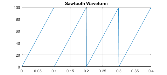
Fig. 370 Continuous Sawtooth Waveform
You need to sample the waveform and store one cycle. Sampled Sawtooth Waveform
shows a sampled version of the sawtooth. You need to generate MAXT samples;
here we show 20 samples, which may be enough. In the code MAXT is set to 100.
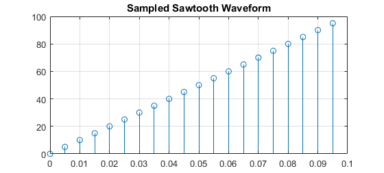
Fig. 371 Sampled Sawtooth Waveform
There’s a lot going on here; let’s take it line by line.
Line |
Explanation |
|---|---|
2-5 |
Standard c-header includes |
7 |
Number for samples in one cycle of the analog waveform |
8 |
Which waveform to use. We’ve defined SAWTOOTH, TRIANGLE and SINE, but you can define your own too. |
10-11 |
Declaring registers |
15-16 |
|
18 |
|
21-24 |
|
26-31 |
|
32-39 |
|
47 |
Here the |
48,49 |
|
50-52 |
Stay on for |
53-55 |
Now turn off for |
Unfiltered Sawtooth Waveform shows the output of the code.
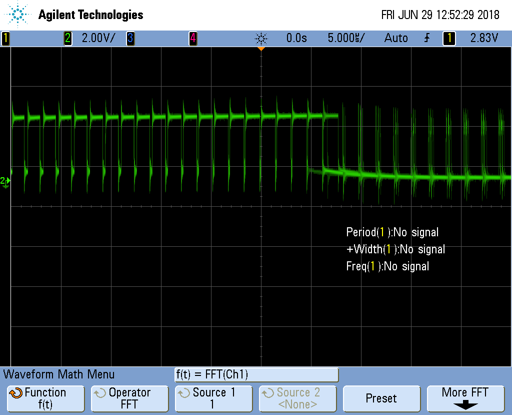
Fig. 372 Unfiltered Sawtooth Waveform
It doesn’t look like a sawtooth; but if you look at the left side you will see each cycle has a longer and longer on time. The duty cycle is increasing. Once it’s almost 100% duty cycle, it switches to a very small duty cycle. Therefore it’s output what we programmed, but what we want is the average of the signal. The left hand side has a large (and increasing) average which would be for top of the sawtooth. The right hand side has a small average, which is what you want for the start of the sawtooth.
A simple low-pass filter, built with one resistor and one capacitor will do it. Low-Pass Filter Wiring Diagram shows how to wire it up.
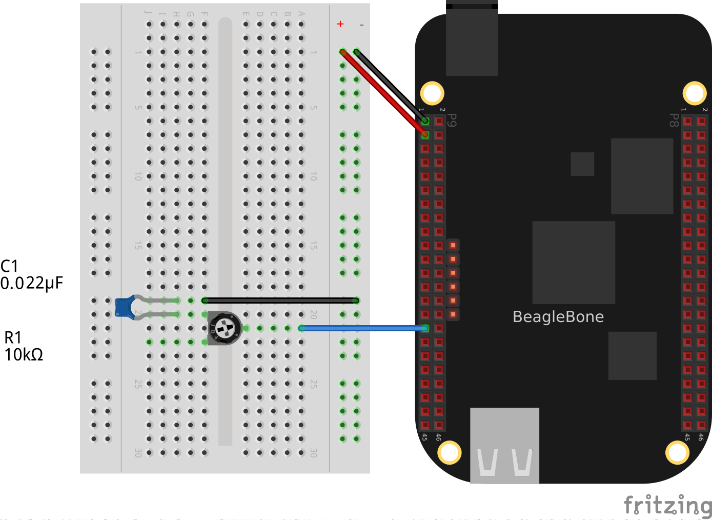
Fig. 373 Low-Pass Filter Wiring Diagram
Note
I used a 10K variable resistor and a 0.022uF capacitor. Probe the circuit between the resistor and the capacitor and adjust the resistor until you get a good looking waveform.
Reconstructed Sawtooth Waveform shows the results for filtered the SAWTOOTH.
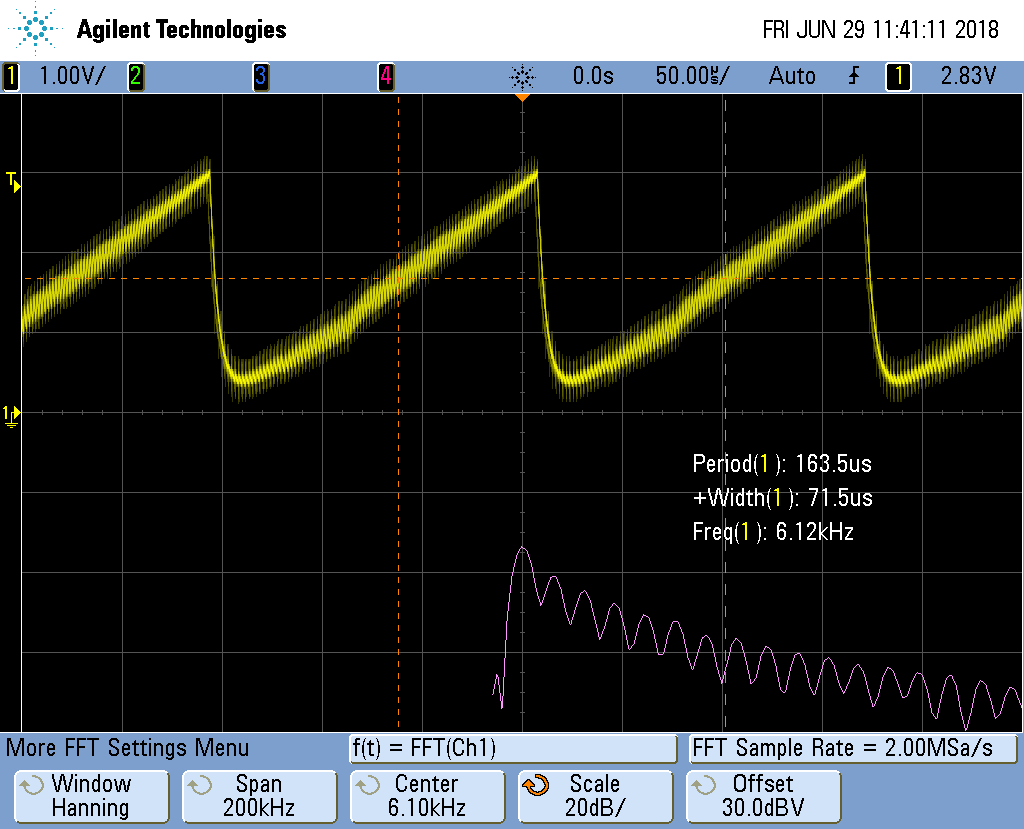
Fig. 374 Reconstructed Sawtooth Waveform
Now that looks more like a sawtooth wave. The top plot is the time-domain plot of the output of the low-pass filter. The bottom plot is the FFT of the top plot, therefore it’s the frequency domain. We are getting a sawtooth with a frequency of about 6.1KHz. You can see the fundamental frequency on the bottom plot along with several harmonics.
The top looks like a sawtooth wave, but there is a high freqnecy superimposed on it. We are only using a simple first-order filter. You could lower the cutoff freqnecy by adjusting the resistor. You’ll see something like Reconstructed Sawtooth Waveform with Lower Cutoff Frequency.
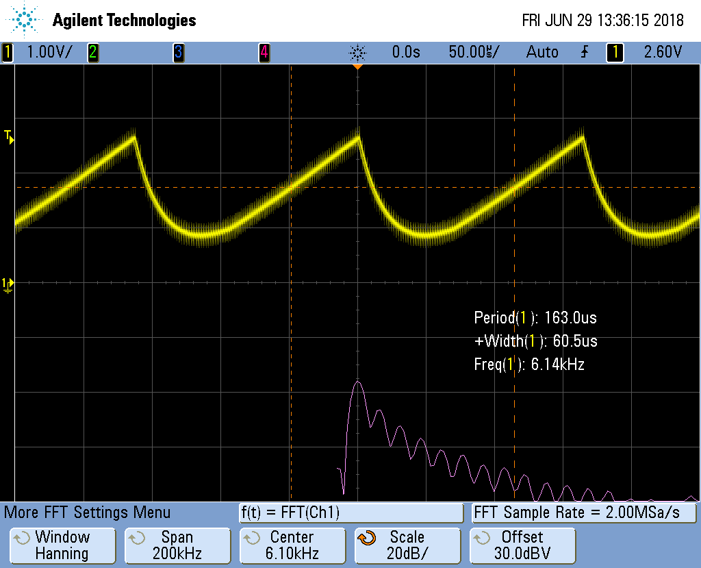
Fig. 375 Reconstructed Sawtooth Waveform with Lower Cutoff Frequency
The high frequencies have been reduced, but the corner of the waveform has been rounded. You can also adjust the cutoff to a higher frequency and you’ll get a sharper corner, but you’ll also get more high frequencies. See Reconstructed Sawtooth Waveform with Higher Cutoff Frequency
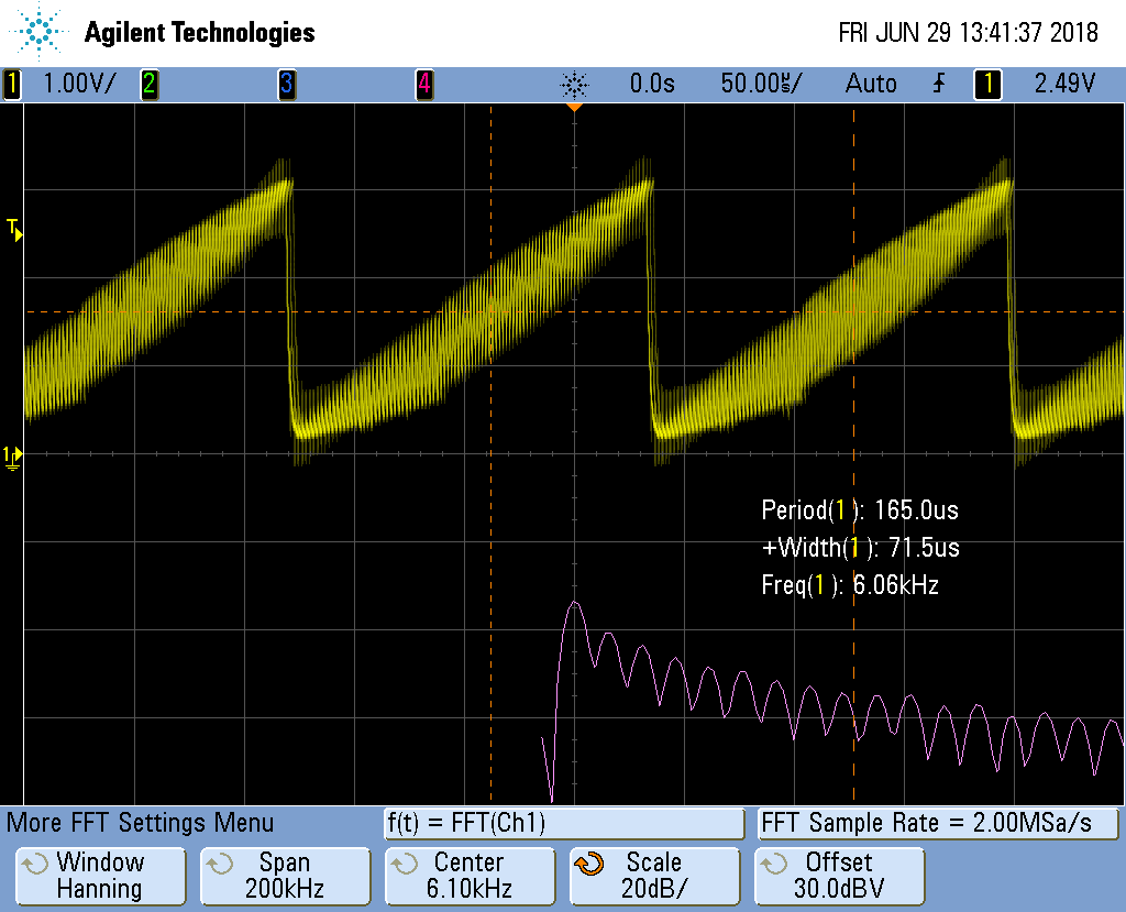
Fig. 376 Reconstructed Sawtooth Waveform with Higher Cutoff Frequency
Adjust to taste, though the real solution is to build a higher order filter. Search for _second order filter and you’ll find some nice circuits.
You can adjust the frequency of the signal by adjusting MAXT. A smaller
MAXT will give a higher frequency. I’ve gotten good results with MAXT
as small as 20.
You can also get a triangle waveform by setting the #define.
Reconstructed Triangle Waveform shows the output signal.
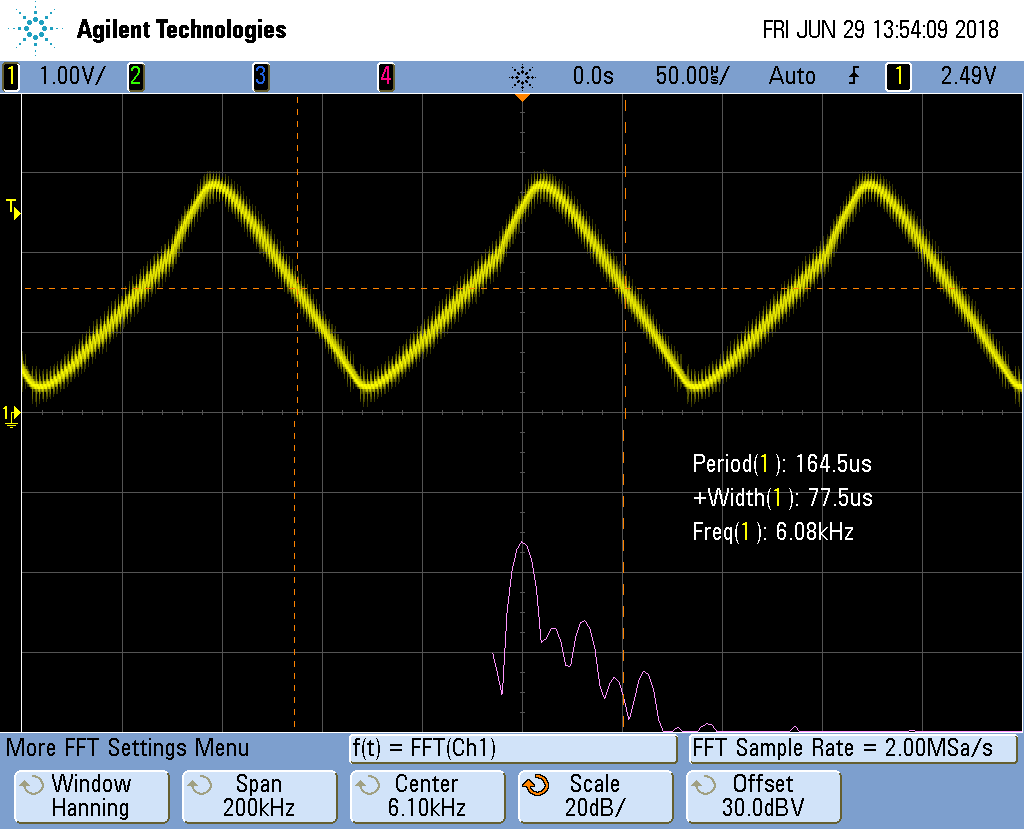
Fig. 377 Reconstructed Triangle Waveform
And also the sine wave as shown in Reconstructed Sinusoid Waveform.
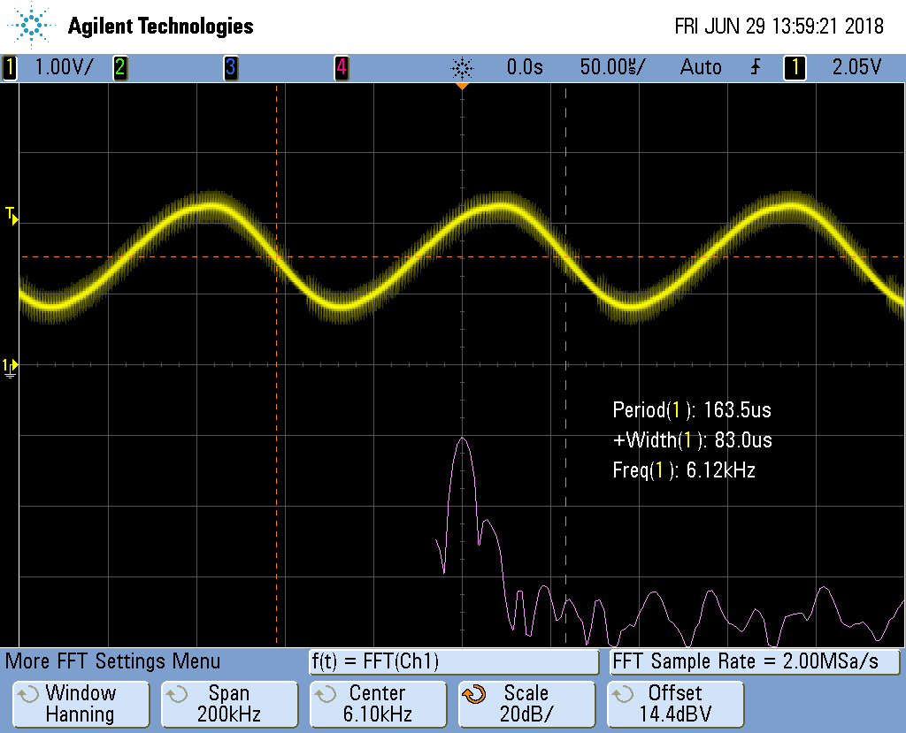
Fig. 378 Reconstructed Sinusoid Waveform
Notice on the bottom plot the harmonics are much more suppressed.
Generating the sine waveform uses floats. This requires much more code. You can look in /tmp/cloud9-examples/sine.pru0.map to see how much memory is being used. blocks_sine_map shows the first few lines for the sine wave.
lines=1..22
Notice line 15 shows 0x18c0 bytes are being used for instructions. That’s 6336 in decimal.
Now compile for the sawtooth and you see only 444 byes are used. Floating-point requires over 5K more bytes. Use with care. If you are short on instruction space, you can move the table generation to the ARM and just copy the table to the PRU.
WS2812 (NeoPixel) driver
Problem
You have an Adafruit NeoPixel LED string or Adafruit NeoPixel LED matrix and want to light it up.
Solution
NeoPixel is Adafruit’s name for the WS2812 Intelligent control LED. Each NeoPixel contains a Red, Green and Blue LED with a PWM controller that can dim each one individually making a rainbow of colors possible. The NeoPixel is driven by a single serial line. The timing on the line is very sensesitive, which make the PRU a perfect candidate for driving it.
Wire the input to P9_29 and power to 3.3V and ground to ground as shown in
NeoPixel Wiring.
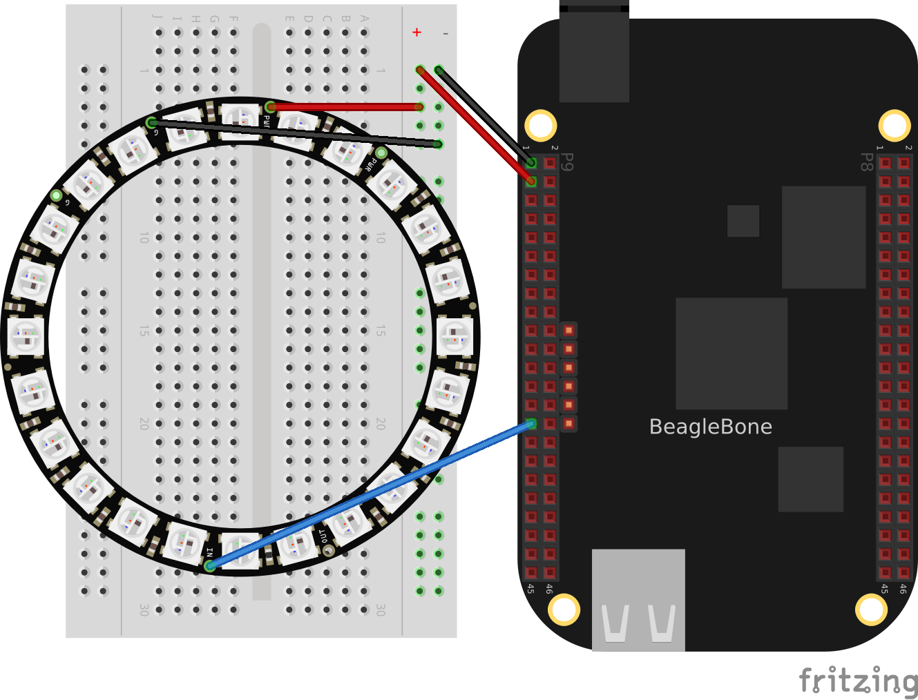
Fig. 379 NeoPixel Wiring
Test your wiring with the simple code in blocks_neo1 which to turns all pixels white.
neo1.pru0.c
Discussion
NeoPixel bit sequence (taken from WS2812 Data Sheet) shows the following waveforms are used to send a bit of data.
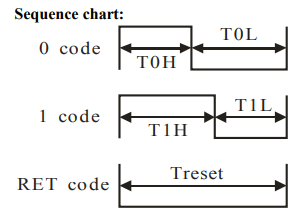
Fig. 380 NeoPixel bit sequence
Label |
Time in ns |
|---|---|
T0H |
350 |
T0L |
800 |
T1H |
700 |
T1L |
600 |
Treset |
>50,000 |
The code in blocks_neo1 define these times in lines 7-10. The /5 is because each instruction take 5ns. Lines 27-30 then set the output to 1 for the desired time and then to 0 and keeps repeating it for the entire string length. NeoPixel zero timing shows the waveform for sending a 0 value. Note the times are spot on.
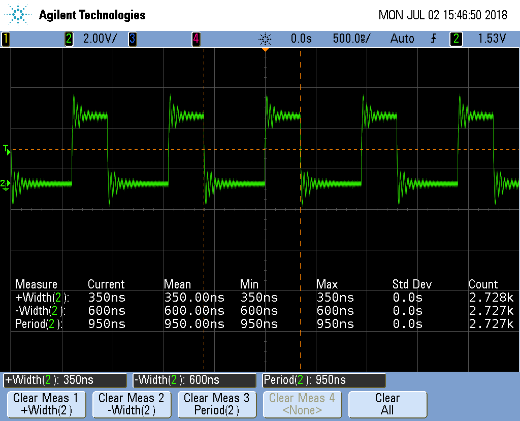
Fig. 381 NeoPixel zero timing
Each NeoPixel listens for a RGB value. Once a value has arrived all other values that follow are passed on to the next NeoPixel which does the same thing. That way you can individually control all of the NeoPixels.
Lines 38-40 send out a reset pulse. If a NeoPixel sees a reset pulse it will grab the next value for itself and start over again.
Setting NeoPixels to Different Colors
Problem
I want to set the LEDs to different colors.
Solution
Wire your NeoPixels as shown in NeoPixel Wiring then run the code in blocks_neo2.
neo2.pru0.c
This will make the first LED green, the second red and the third blue.
Discussion
NeoPixel data sequence shows the sequence of bits used to control the green, red and blue values.

Fig. 382 NeoPixel data sequence
Note
The usual order for colors is RGB (red, green, blue), but the NeoPixels use GRB (green, red, blue).
Line-by-line for neo2.pru0.c is the line-by-line for neo2.pru0.c.
Line 23 |
Explanation Define the string of colors to be output. Here the ordering of the bits is the same as NeoPixel data sequence, GRB. |
26 |
Loop for each color to output. |
27 |
Loop for each bit in an GRB color. |
28 |
Get the j^th^ color and mask off all but the i^th^ bit. (0x1:ref:`i) takes the value 0x1 and shifts it left i bits. When anded (&) with color[j] it will zero out all but the i^th^ bit. If the result of the operation is 1, the if is done, otherwise the else is done. |
29-32 |
Send a 1. |
34-37 |
Send a 0. |
42-43 |
Send a reset pulse once all the colors have been sent. |
Note
This will only change the first STR_LEN LEDs. The LEDs that follow will not be changed.
Controlling Arbitrary LEDs
Problem
I want to change the 10^th^ LED and not have to change the others.
Solution
You need to keep an array of colors for the whole string in the PRU. Change the color of any pixels you want in the array and then send out the whole string to the LEDs. blocks_neo3 shows an example animates a red pixel running around a ring of blue background. Neo3 Video shows the code in action.
neo3.pru0.c
Neo3 Video
Discussion
Line |
Explanation |
|---|---|
32,33 |
Initiallize the array of colors. |
38-41 |
Update the array. |
44-58 |
Send the array to the LEDs. |
60-61 |
Send a reset. |
64 |
Wait a bit. |
Controlling NeoPixels Through a Kernel Driver
Problem
You want to control your NeoPixels through a kernel driver so you can control it
through a /dev interface.
Solution
The rpmsg_pru driver provides a way to pass data between the ARM processor and the PRUs. It’s already included on current images. blocks_neo4 shows an example.
neo4.pru0.c
Run the code as usual.
bone$ make TARGET=neo4.pru0
/var/lib/cloud9/common/Makefile:29: MODEL=TI_AM335x_BeagleBone_Black,TARGET=neo4.pru0
-    Stopping PRU 0
-     copying firmware file /tmp/cloud9-examples/neo4.pru0.out to /lib/firmware/am335x-pru0-fw
write_init_pins.sh
-    Starting PRU 0
MODEL   = TI_AM335x_BeagleBone_Black
PROC    = pru
PRUN    = 0
PRU_DIR = /sys/class/remoteproc/remoteproc1

bone$ echo 0 0xff 0 127 > /dev/rpmsg_pru30
bone$ echo -1 > /dev/rpmsg_pru30
/dev/rpmsg_pru30 is a device driver that lets the ARM talk to the PRU.
The first echo says to set the 0^th^ LED to RGB value 0xff 0 127. (Note: you can
mix hex and decimal.) The second echo tells the driver to send the data to the
LEDs. Your 0^th^ LED should now be lit.
Discussion
There’s a lot here. I’ll just hit some of the highlights in Line-by-line for neo4.pru0.c.
Line |
Explanation |
|---|---|
30 |
The CHAN_NAME of rpmsg-pru matches that prmsg_pru driver that is is already installed. This connects this PRU to the driver. |
32 |
The CHAN_PORT tells it to use port 30. That’s why we use /dev/rpmsg_pru30 |
40 |
payload[] is the buffer that receives the data from the ARM. |
42-48 |
Same as the previous NeoPixel examples. |
52 |
color[] is the state to be sent to the LEDs. |
66-68 |
color[] is initialized. |
70-85 |
Here are a number of details needed to set up the channel between the PRU and the ARM. |
88 |
Here we wait until the ARM sends us some numbers. |
99 |
Receive all the data from the ARM, store it in payload[]. |
101-111 |
The data sent is: index red green blue. Pull off the index. If it’s in the right range, pull off the red, green and blue values. |
113 |
The NeoPixels want the data in GRB order. Shift and OR everything together. |
116-133 |
If the index = -1, send the contents of color to the LEDs. This code is same as before. |
You can now use programs running on the ARM to send colors to the PRU.
blocks_neo-rainbow shows an example.
neo-rainbow.py
Line 19 writes the data to the PRU. Be sure to have a newline, or space after the last number, or you numbers will get blurred together.
Switching from pru0 to pru1 with rpmsg_pru
There are three things you need to change when switching from pru0 to pru1 when using rpmsg_pru.
The include on line 10 is switched to
#include "resource_table_1.h"(0 is switched to a 1)Line 17 is switched to
#define HOST_INT ((uint32_t) 1 << 31)(30 is switched to 31.)Lines 23 and 24 are switched to:
#define TO_ARM_HOST                   18
#define FROM_ARM_HOST         19
These changes switch to the proper channel numbers to use pru1 instead of pru0.
RGB LED Matrix - No Integrated Drivers
Problem
You have a RGB LED matrix (RGB LED Matrix – No Integrated Drivers (Falcon Christmas)) and want to know at a low level how the PRU works.
Solution
Here is the datasheet, but the best description I’ve found for the RGB Matrix is from Adafruit. I’ve reproduced it here, with adjustments for the 64x32 matrix we are using.
information
There’s zero documentation out there on how these matrices work, and no public datasheets or spec sheets so we are going to try to document how they work.
First thing to notice is that there are 2048 RGB LEDs in a 64x32 matrix. Like pretty much every matrix out there, you can’t drive all 2048 at once. One reason is that would require a lot of current, another reason is that it would be really expensive to have so many pins. Instead, the matrix is divided into 16 interleaved sections/strips. The first section is the 1^st^ ‘line’ and the 17^th^ ‘line’ (64 x 2 RGB LEDs = 128 RGB LEDs), the second is the 2^nd^ and 18^th^ line, etc until the last section which is the 16^th^ and 32^nd^ line. You might be asking, why are the lines paired this way? wouldn’t it be nicer to have the first section be the 1^st^ and 2^nd^ line, then 3^rd^ and 4^th^, until the 15^th^ and 16^th^? The reason they do it this way is so that the lines are interleaved and look better when refreshed, otherwise we’d see the stripes more clearly.
So, on the PCB is 24 LED driver chips. These are like 74HC595s but they have 16 outputs and they are constant current. 16 outputs * 24 chips = 384 LEDs that can be controlled at once, and 128 * 3 (R G and B) = 384. So now the design comes together: You have 384 outputs that can control one line at a time, with each of 384 R, G and B LEDs either on or off. The controller (say an FPGA or microcontroller) selects which section to currently draw (using LA, LB, LC and LD address pins - 4 bits can have 16 values). Once the address is set, the controller clocks out 384 bits of data (48 bytes) and latches it. Then it increments the address and clocks out another 384 bits, etc until it gets to address #15, then it sets the address back to #0
https://cdn-learn.adafruit.com/downloads/pdf/32x16-32x32-rgb-led-matrix.pdf
That gives a good overview, but there are a few details missing. blocks_rgb_python is a functioning python program that gives a nice high-level view of how to drive the display.
rgb_python.py
Be sure to run the blocks_rgb_setup script before running the python code.
rgb_python_setup.sh
Make sure line 29 is commented out and line 30 is uncommented. Later we’ll configure for _pruout_, but for now the python code doesn’t use the PRU outs.
# config-pin $pin pruout
config-pin $pin out
Your display should look like Display running rgb_python.py.
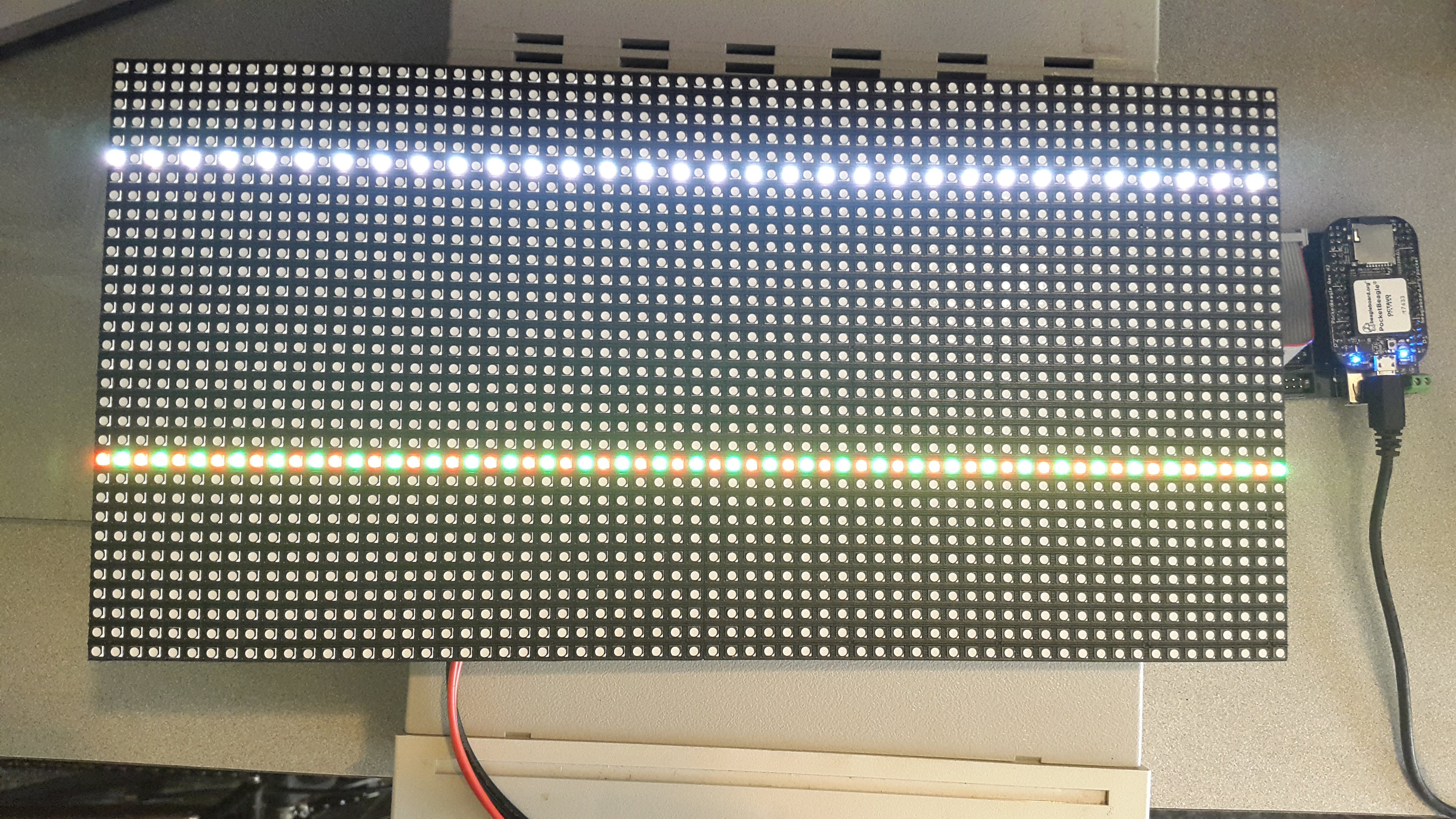
Fig. 383 Display running rgb_python.py
So why do only two lines appear at a time? That’s how the display works. Currently lines 6 and 22 are showing, then a moment later 7 and 23 show, etc. The display can only display two lines at a time, so it cycles through all the lines. Unfortunately, python is too slow to make the display appear all at once. Here’s where the PRU comes in.
:ref:blocks_rgb1 is the PRU code to drive the RGB LED matrix.
Be sure to run bone$ source rgb_setup.sh first.
rgb1.pru0.c
The results are shown in Display running rgb1.c on PRU 0.
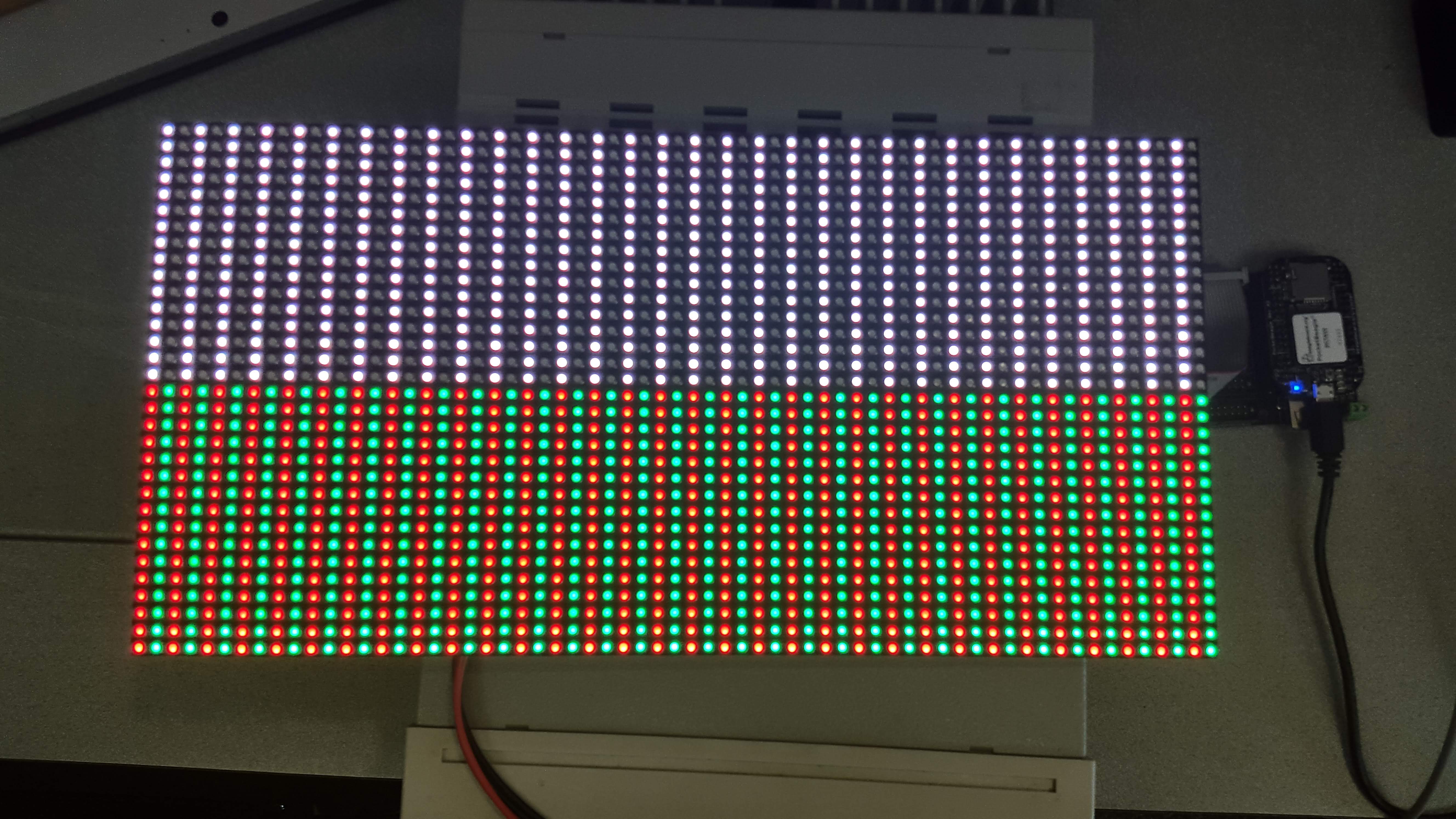
Fig. 384 Display running rgb1.c on PRU 0
The PRU is fast enough to quickly write to the display so that it appears as if all the LEDs are on at once.
Discussion
There are a lot of details needed to make this simple display work. Let’s go over some of them.
First, the connector looks like RGB Matrix J1 connector.
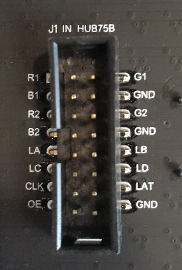
Fig. 385 RGB Matrix J1 connector
Notice the labels on the connect match the labels in the code. PocketScroller pin table shows how the pins on the display are mapped to the pins on the PocketBeagle.
J1 Connector Pin |
Pocket Headers |
gpio port and bit number |
Linux gpio number |
PRU R30 bit number |
|---|---|---|---|---|
R1 |
P2_10 |
1-20 |
52 |
|
B1 |
P2_06 |
1-25 |
57 |
|
R2 |
P2_04 |
1-26 |
58 |
|
B2 |
P2_01 |
1-18 |
50 |
|
LA |
P2_32 |
3-16 |
112 |
PRU0.2 |
LC |
P1_31 |
3-18 |
114 |
PRU0.4 |
CLK |
P1_33 |
3-15 |
111 |
PRU0.1 |
OE |
P1_29 |
3-21 |
117 |
PRU0.7 |
G1 |
P2_08 |
1-28 |
60 |
|
G2 |
P2_02 |
1-27 |
59 |
|
LB |
P2_30 |
3-17 |
113 |
PRU0.3 |
LD |
P2_34 |
3-19 |
115 |
PRU0.5 |
LAT |
P1_36 |
3-14 |
110 |
PRU0.0 |
The J1 mapping to gpio port and bit number comes from https://github.com/FalconChristmas/fpp/blob/master/capes/pb/panels/PocketScroller.json. The gpio port and bit number mapping to Pocket Headers comes from https://docs.google.com/spreadsheets/d/1FRGvYOyW1RiNSEVprvstfJAVeapnASgDXHtxeDOjgqw/edit#gid=0.
Oscilloscope display of CLK, OE, LAT and R1 shows four of the signal waveforms driving the RGB LED matrix.
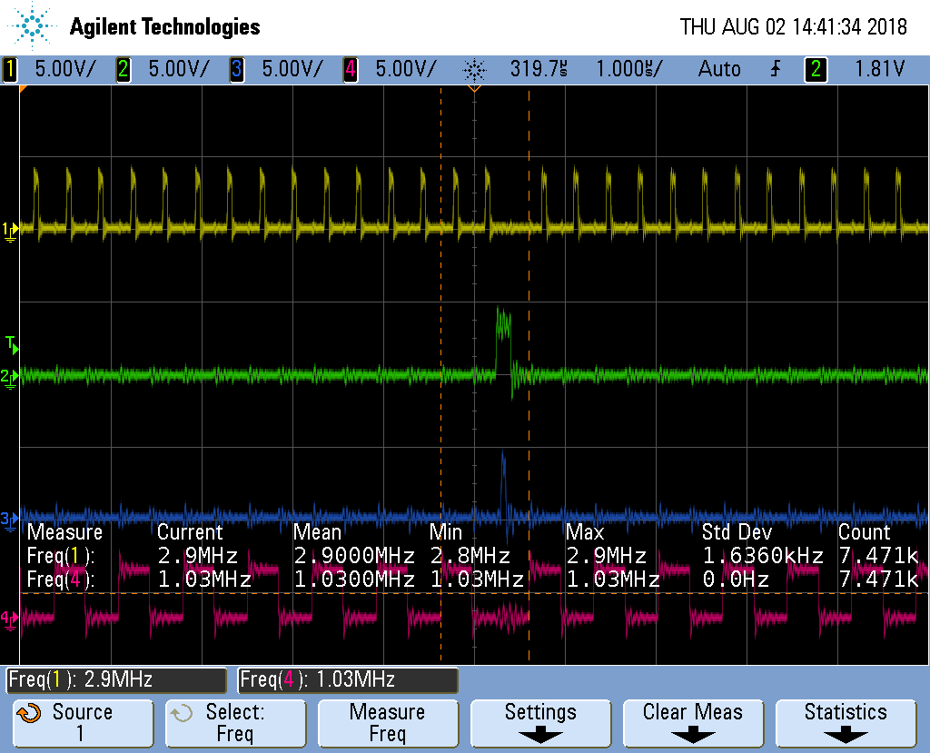
Fig. 386 Oscilloscope display of CLK, OE, LAT and R1
The top waveform is the CLK, the next is OE, followed by LAT and finally R1. The OE (output enable) is active low, so most of the time the display is visible. The sequence is:
Put data on the R1, G1, B1, R2, G2 and B2 lines
Toggle the clock.
Repeat the first two steps as one row of data is transferred. There are 384 LEDs (2 rows of 32 RGB LEDs times 3 LED per RGB), but we are clocking in six bits (R1, G1, etc.) at a time, so 384/6=64 values need to be clocked in.
Once all the values are in, disable the display (OE goes high)
Then toggle the latch (LAT) to latch the new data.
Turn the display back on.
Increment the address lines (LA, LB, LC and LD) to point to the next rows.
Keep repeating the above to keep the display lit.
Using the PRU we are able to run the clock a about 2.9 MKHz. FPP waveforms shows the optimized assembler code used by FPP clocks in at some 6.3 MHz. So the compiler is doing a pretty good job, but you can run some two times faster if you want to use assembly code. In fairness to FPP, it’s having to pull it’s data out of RAM to display it, so isn’t not a good comparison.
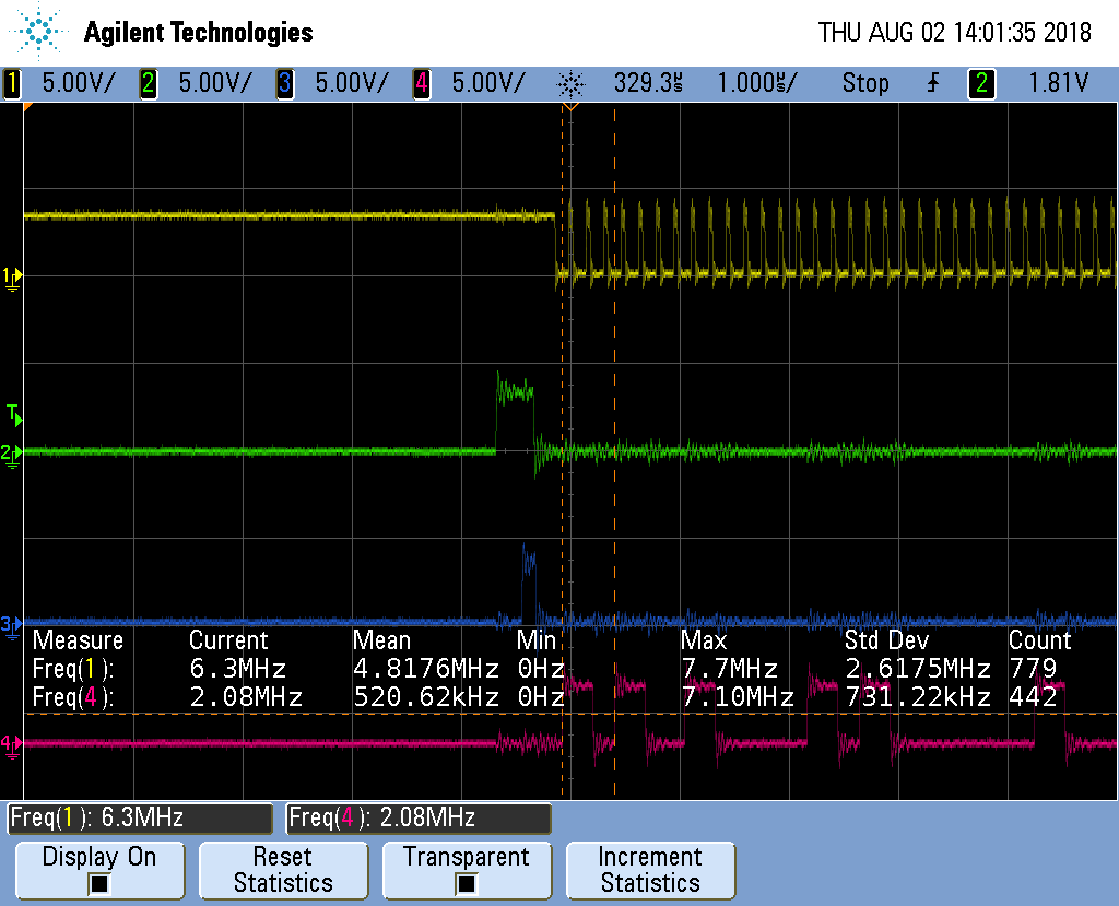
Fig. 387 FPP waveforms
Getting More Colors
The Adafruit description goes on to say:
information
The only downside of this technique is that despite being very simple and fast, it has no PWM control built-in! The controller can only set the LEDs on or off. So what do you do when you want full color? You actually need to draw the entire matrix over and over again at very high speeds to PWM the matrix manually. For that reason, you need to have a very fast controller (50 MHz is a minimum) if you want to do a lot of colors and motion video and have it look good.
https://cdn-learn.adafruit.com/downloads/pdf/32x16-32x32-rgb-led-matrix.pdf
This is what FPP does, but it’s beyond the scope of this project.
Compiling and Inserting rpmsg_pru
Problem
Your Beagle doesn’t have rpmsg_pru.
Solution
Do the following.
bone$ *cd 05blocks/code/module*
bone$ *sudo apt install linux-headers-\`uname -r`*
bone$ *wget https://github.com/beagleboard/linux/raw/4.9/drivers/rpmsg/rpmsg_pru.c*
bone$ *make*
make -C /lib/modules/4.9.88-ti-r111/build M=$PWD
make[1]: Entering directory '/usr/src/linux-headers-4.9.88-ti-r111'
  LD      /home/debian/PRUCookbook/docs/05blocks/code/module/built-in.o
  CC [M]  /home/debian/PRUCookbook/docs/05blocks/code/module/rpmsg_client_sample.o
  CC [M]  /home/debian/PRUCookbook/docs/05blocks/code/module/rpmsg_pru.o
  Building modules, stage 2.
  MODPOST 2 modules
  CC      /home/debian/PRUCookbook/docs/05blocks/code/module/rpmsg_client_sample.mod.o
  LD [M]  /home/debian/PRUCookbook/docs/05blocks/code/module/rpmsg_client_sample.ko
  CC      /home/debian/PRUCookbook/docs/05blocks/code/module/rpmsg_pru.mod.o
  LD [M]  /home/debian/PRUCookbook/docs/05blocks/code/module/rpmsg_pru.ko
make[1]: Leaving directory '/usr/src/linux-headers-4.9.88-ti-r111'
bone$ *sudo insmod rpmsg_pru.ko*
bone$ *lsmod | grep rpm*
rpmsg_pru               5799  2
virtio_rpmsg_bus       13620  0
rpmsg_core              8537  2 rpmsg_pru,virtio_rpmsg_bus
It’s now installed and ready to go.
copyright.c